The current (May) issue of Road & Track had a brief column discussing carbon buildup on intake valves on engines that use a direct injection (compared to port injection) fuel system. It mentions installing a catch can to trap oil vapors that are being recycled into the intake via the PCV valve. I'm aware of some other car forums (which cars use port injection) where the use of catch cans has been discussed, apparently with significant results. Since this is my first vehicle with direct injection, I'm wondering how Ford addressed this (if they did at all). And if I wanted to install a catch can, where one could place it in that nightmare under the hood
![Image]()
. Has anyone given any thought to this? Ford, if you're out there, can you chime in? Inquiring minds want to know....

Concern about carbon buildup on intake valves?
wamara
41 - 60 of 232 Posts
Joined
·
144 Posts
Well we don't know that necessarily. But what I DO know is that with two very modified vehicles I have use breather cans. Both have been driven to over 150,000 miles. And both were completely factory engines. Never had an issue. (Though I did change my oil at least every 3000 miles). I also can say I dropped my fair share of intercooler pipes and I never saw oil in the intake pipes with a breather can on mine. Other cars without them absolutely.And that not only will not pass any emissions, it will greatly reduce engine life as your leaving in all the combustion by-products that must be evacuated as soon as they enter the crankcase and are still in a suspended or gaseous state.
As far as emissions, well I live in PA and that part of the inspection is entirely visual. Just reconnect the rubber lines and you will always pass. Other states I don't know about.
We also do know that those intake gasses and oil run hell on your valves and guides over time on a DI engine.
For me, at least, I think the lesser of two evils is common sense here.
")
On the other hand, with 40 years of direct experience in demanding high profile venues, if anyone is going to have a better solution to an impending problem it would be you. So I'm all ears!
Joined
·
17 Posts
2 members contacted us to see if we would come on and enter a discussion on the issues with direct injection and the related issues. We do have a F150 EcoBoost 3.5 twin turbo. There are 2 other cans on the market that catch most of the oil mix as well, the SMC (Saiku Micchi), the ELite E2, and the Apex (a copy of the Elite E2). Routing and the use of checkvalves to prevent any boost pressure entering the crankcase are critical. As for the rest, most are only 10-30% effective so although they capture oil (even a beer can or mayonnaise jar will as well), they are letting most pass right through so they are little more than placebo's. Carb cert is in the future.Tuner Boost, first off if your product can get CARB certified for our Escapes I would be interested. Second what brings you to this board? Do you have an Escape? If you don't theirs nothing wrong with that, I've enjoyed your posts, but if your here just to pimp your wares I think full disclosure is in order. If you have an Escape that's great as you have incentive to help in our quest for an all around better driving experience.
Thanks
Mark
What one can do is a manual intake valve cleaning to restore the valve shape to original and see the improvement in power and smoothness. It is not difficult, it just takes time. Make sure all ports are taped off to avoid any debris from entering, and bring the one your cleaning up to TDC to make sure both valves are closed. Use compressed air and a shop vac to remove the debris as your cleaning. A die grinder or cordless drill with some long shaft brushes will allow you to get at all sides of the valves and intake port. When clean, blow debris clear and tape off and move to the next. Just take your time when removing and reinstalling the IM...the O-ring gaskets are reuseable many times, so only need to get the brush set. Amazon has many to choose from.
Your correct if you are changing oil often enough....but a simple BlackStone oil analysis will show the level of contaminates accumulating in the oil. I am referring to the actual wear on all moving parts over time. Most would not know the rate of wear w/out a tear down. When you do tear down, look closely at the bearings and journals. Those little "worm track" stains are the sulfuric acid attacking the bearing surface and the case hardened journal surface. Look on the valve train components....rocker arms with roller bearings (most modern engines or any after market) and you will see the corrosion attacking them as water and acid condense under the valve covers. This example is from only 6 months of breather alone:Well we don't know that necessarily. But what I DO know is that with two very modified vehicles I have use breather cans. Both have been driven to over 150,000 miles. And both were completely factory engines. Never had an issue. (Though I did change my oil at least every 3000 miles). I also can say I dropped my fair share of intercooler pipes and I never saw oil in the intake pipes with a breather can on mine. Other cars without them absolutely.
As far as emissions, well I live in PA and that part of the inspection is entirely visual. Just reconnect the rubber lines and you will always pass. Other states I don't know about.
We also do know that those intake gasses and oil run hell on your valves and guides over time on a DI engine.
For me, at least, I think the lesser of two evils is common sense here.
On the other hand, with 40 years of direct experience in demanding high profile venues, if anyone is going to have a better solution to an impending problem it would be you. So I'm all ears!
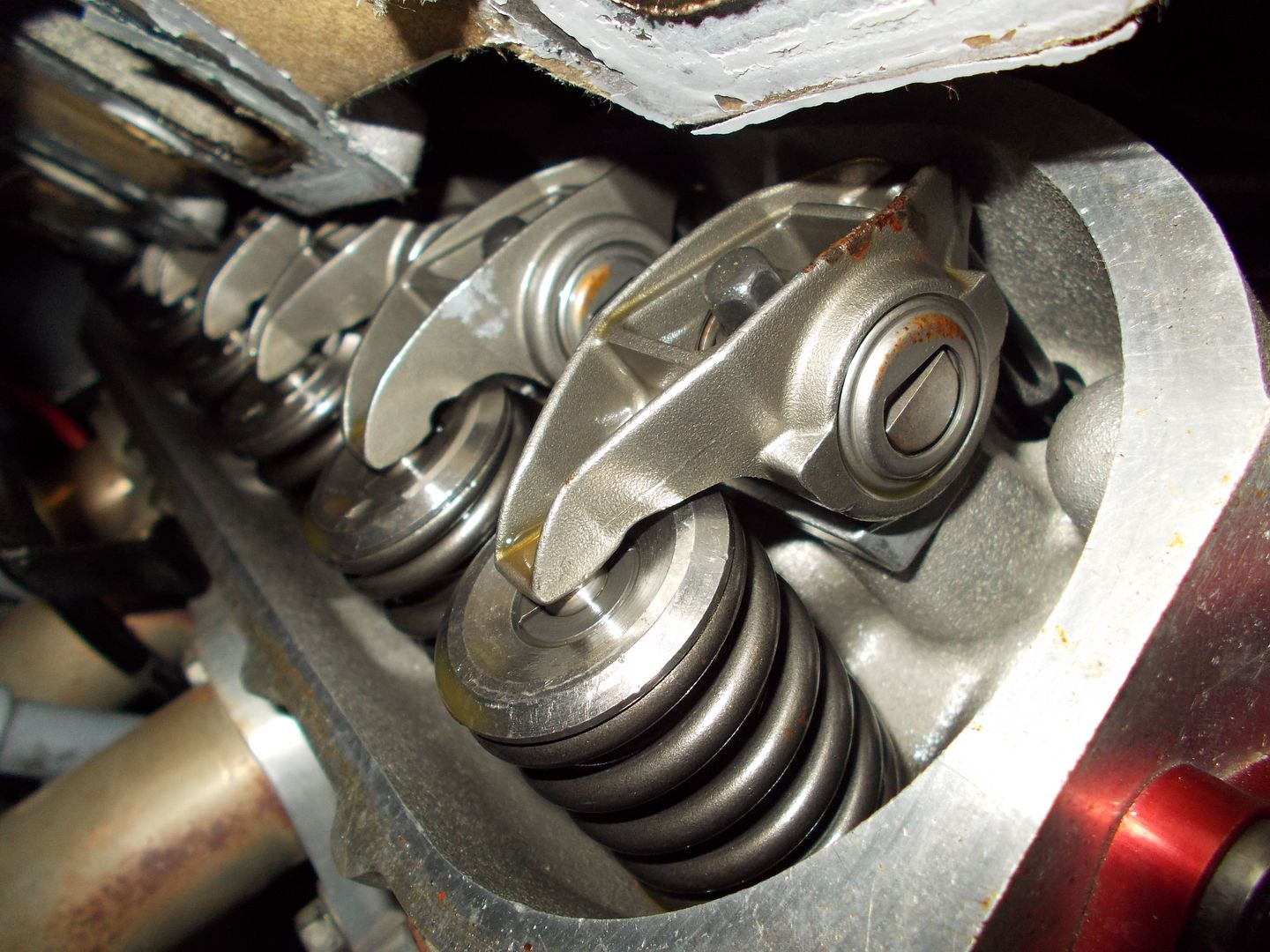
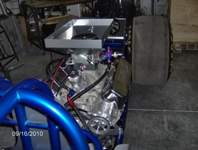
With all our race engines we run belt driven vacuum pumps to ensure immediate evacuation of all of this and also try to maintain 14-15" of vacuum to aid ring seal. This allows us to run a low tension ring as well for less resistance. We dont want ANY oil ingested and these engines have to repeat round after round as we win or lose far too often by 1/1000th of a second or less:
We constantly have DI engines in here for re-ring and/or intake valve/guide issues from this:

This is what you will find is evacuated and caught vs just venting:
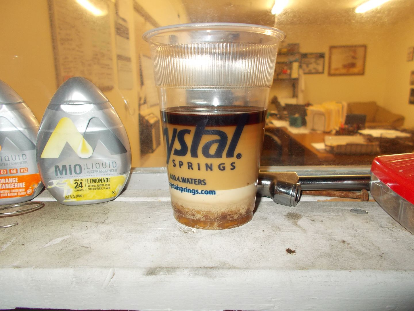
Bottom layer settles to be mainly sulfuric acid and water, then unburnt fuel and water emulsified, then water and oil emulsified, and the very top oil alone settles out. Not what you want in the oil. We always have examples of engines that go miles against all odds, the occasional car comes in with no oil change for 50k miles and still runs fine not burning oil, etc. and the time a guys wife got in his new truck that he was doing the 1st change at 1000 miles and starts it up and drives off with no oil in it (the drain pan still under the truck), drives 20 miles to town, shops and drives back home clacking and rattling like crazy. He fills the oil and gradually all lifters free up and get quiet....last I talked to him he had close to 200k miles on it but the body was rusting off (WI). Aside from burning a qt every 2k miles, he says it ran fine. So, as a Professional race team owner, we look at every way possible to extend the life of not only the race engines that may be $20-$45k each, but the tow vehicles as well. So yes, you may very well get long life out of the engine, but it could have been better.
And have developed several FI systems for the new DI engines:

So, to understand crankcase evacuation, all engines need a filtered (and if MAF equipped a MAF metered source) fresh, or cleanside source that brings in clean air to make up for the foul/dirty air pulled out. This also aids in "flushing" these damaging compounds out. This clean air travels through the crankcase flushing the damaging foul vapors out the opposite side of the crankcase. Similar to a smoke filled room that has a vent filling it with smoke. Open on window and you relieve pressure and some smoke escapes, but until you can open a window on the opposite end, and have a fan pulling (evacuating) that smoke out, the room can never clear. The crankcase is similar. Most only think in terms of relieving pressure and are not aware of the damaging combustion by-products constantly entering as blow-by. They must be removed before they can settle and mix with the oil. And yes, a motor may still run and seem OK, but the increased wear does occur and can be seen when you tear down.
Good dialog here!! Keep it coming!
Joined
·
17 Posts
Here is a person w/an ecoboost that does regular oil analysis reporting the before and after. If the images dont post I will try and get them to add later:
Recent Blackstone analysis
Here is my Blackstone analysis supporting that my fuel% has came down to normal amounts after completing the rx system 100% thats including drilling both turbo pipes. IMHO this is the only route that will do what needs to be done on this 3.5l eco. All other attempts are not fully meeting the standard the rx does. I have done extensive research and I wouldn't run any other can then rx. Fuel % before completing rx system 2.5%
Fuel% after rx system 1%
Click this bar to view the full image.
Name: uploadfromtaptalk1415642122312.jpg
Views: 8
Size: 206.7 KB
Click this bar to view the full image.
Name: uploadfromtaptalk1415642122312.jpg
Views: 8
Size: 206.7 KB this is about 3/4 of my catch since installing the rx
MPT tuned
13.25@106.10 & 13.31@106.93
Attached Images Attached Images
Hope this gives a picture into just one part of what accumulates in greater then acceptable amounts in the engine oil.
Joined
·
2,051 Posts
So...I'm looking at getting a 2015 Escape Ti 2.0L. I come from the MS3 MZR di engine, Cobalt SS turbo w/ di, and familiar with BMW's walnut blasting. All is true as stated by Tuner Boost. These DI turbo engines with pcv venting back into the intake are an issue. The canadian race shop for my CSS makes a oil separator but those cheap *** ebay ones will not do the trick. You can get your own media sprayer and blow walnuts in, just a ****. If I do pull the trigger on this escape Ti. I WILL BE using a oil separator. My CSS is a 2009 w/ 35k miles as it is summer only track car, I haven't seen inside the heads yet, but sometimes it can do that stupid idle crap.
EDIT: I should say, anyone with a ecoboost, just remove the intake tube and look inside that lip and turbo, you'll see a puddle of oil... which....you don't want. That crap is just going right back in the intake.
What about oil affecting the MAF or map sensors? See any of those blowing up?Many in the CSS world that go big turbo, or with tune switch to a relocated maf on the cold side pipe of the IC.
I'm sold, I'm sold ... so how 'bout some help on how to specifically connect the catch can on our 2.0 Ecoboost FE ;-)
Lot's of technical Q's here in post #40 http://www.fordescape.org/forum/400593-post40.html
I popped the hood, pulled the engine cover and prowled a bit today ..... our PCV system / underhood vacuum line and intake air pipe arrangement really doesn't correlate well to the available examples. I'm no mechanical fool but this is a system I've not explored in detail before so case-specific education needed, please.
Joined
·
2,051 Posts
Let me see if I can get some pics of the setup in the CSS 2.0. He has NICE quick fittings, you pay for it, but it isn't a hack job.I'm sold, I'm sold ... so how 'bout some help on how to specifically connect the catch can on our 2.0 Ecoboost FE ;-)
http://www.fordescape.org/forum/400593-post40.html
I popped the hood, pulled the engine cover and prowled a bit today ..... our PCV system / underhood vacuum line and intake air pipe arrangement really doesn't correlate well to the available examples. I'm no mechanical fool but this is a system I've not explored in detail before so case-specific education needed, please.
^^^ Thanks, that might be interesting, but except perhaps in concept a Chevy Cobalt isn't the same as the 2.0 FE underhood. The devil is in the details ;-)
Joined
·
2,051 Posts
Here is the Powell LNF PCV Anti-coking drain back system
The seperator has a filter, and a check valve, and is designed to maintain OEM design intent vacuum through the PCV system.
![Image]()
![Image]()
![Image]()
![Image]()
If nothing great comes up for the FE I'll retro fit this one.
The seperator has a filter, and a check valve, and is designed to maintain OEM design intent vacuum through the PCV system.


If nothing great comes up for the FE I'll retro fit this one.
Joined
·
2,051 Posts
I haven't seen the 2.0 without the plastic engine cover, but I bet it is 99% the same setup just a different manufacture.^^^ Thanks, that might be interesting, but except perhaps in concept a Chevy Cobalt isn't the same as the 2.0 FE underhood. The devil is in the details ;-)
Also those cheap canisters only have steel wool inside "to grab oil and particles", not really the best method.
Joined
·
17 Posts
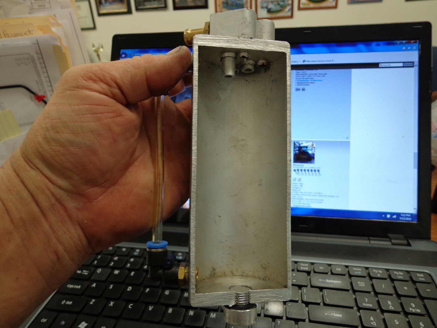
Get good pics up and a diagram & I can guide any on proper routing. The drain back cans are NOT to ever be used....along with the oil, they are catching the water, unburnt fuel, abrasive soot and carbon, and sulfuric acid and when you return it you have defeated tone of the critical functions of the PCV system, removing these before they can drop and mix with the oil. Do an oil analysis to see first hand. It will take 20-40-60k miles, but you will ruin the bearings and most of the rest of the internal parts if you re-introduce that concentrate of gunk back into the crankcase. Here are pictures of many cans (have been buying everyone on the market, testing and cutting them apart for the past 13 years):
![Image]()
![Image]()
![Image]()
![Image]()
![Image]()
![Image]()
![Image]()
![Image]()
![Image]()
The only way to really know is to test the can. Take any can and install it. Now install one of the ones that do catch all or nearly all the gunk in line after the can your testing. Then do so in reverse. This will give you an accurate result. Here is one done by a UPR customer (same can as Moroso, Billet Prototypes, and a few dozen others made by one manufacturer but with tons of brand labels on them) with UPR supporting the customer during the test over several months and thousands of miles (we did not have anything to do with this except answer tech questions). Follow it closely and this can be done with any can to see how effective it is, or if it just allows most to pass right through. Most assume the can they chose is doing a good job and never test to see just how good. This was done on a 5.0 F150, and the person doing the test did it in a very controlled and detailed manner:
5.0 UPR vs RX Catch Can Effectiveness Test
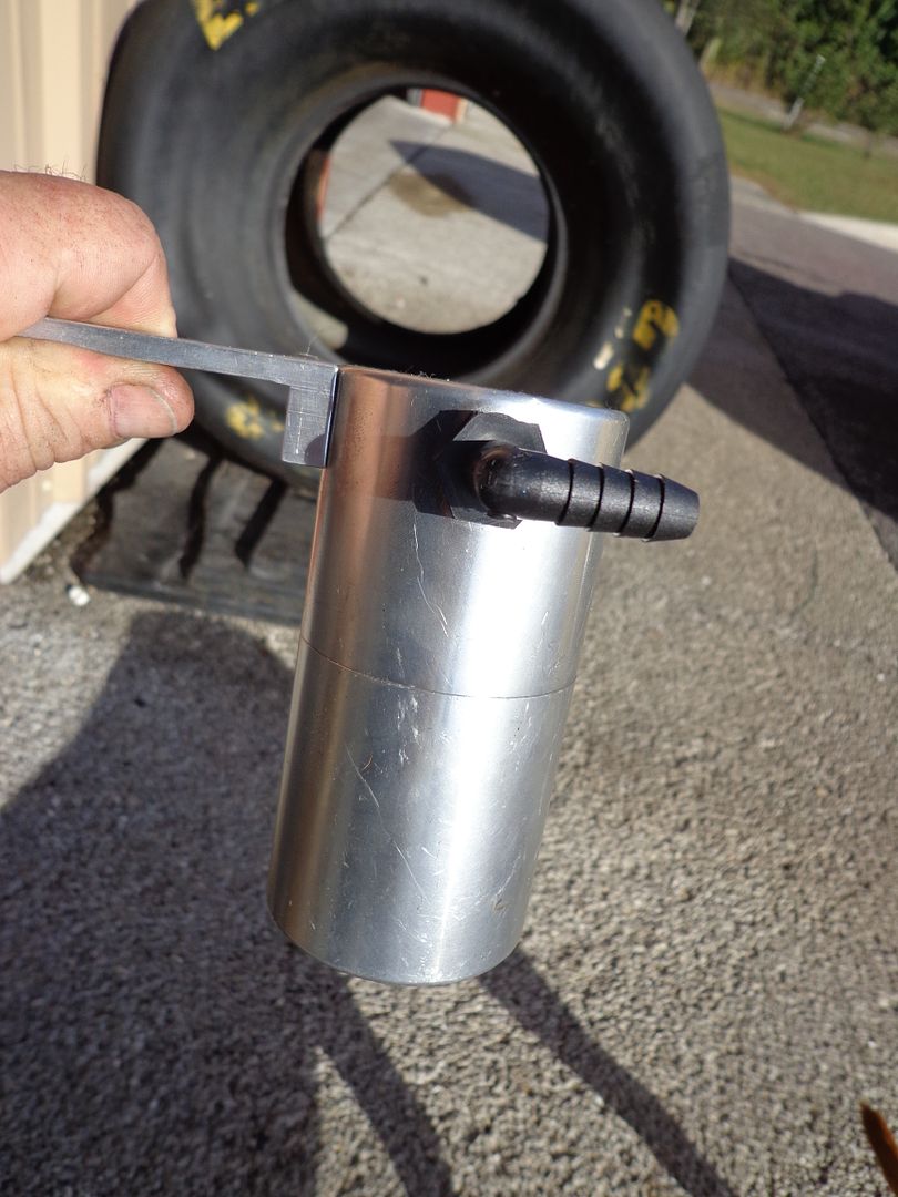
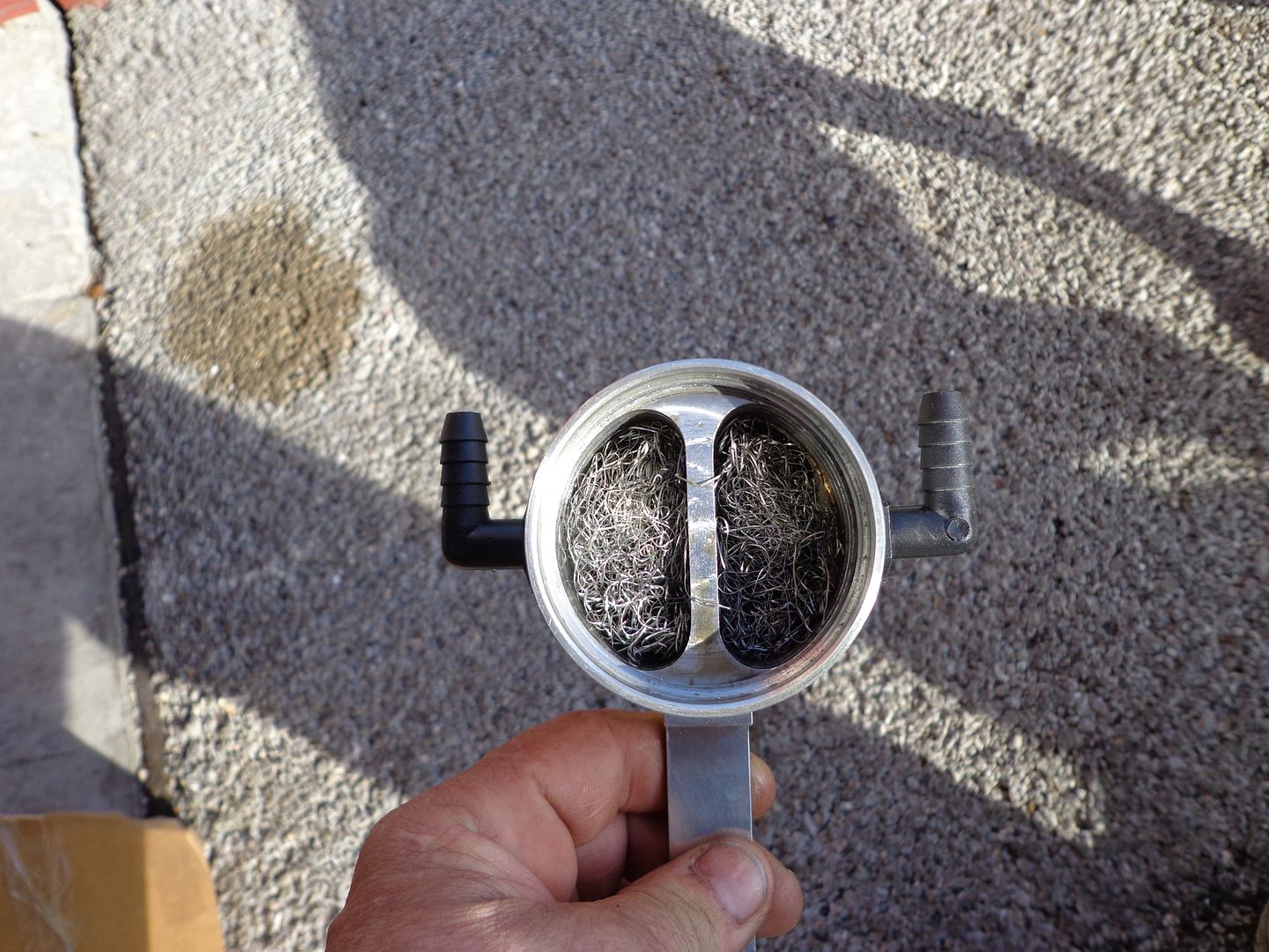
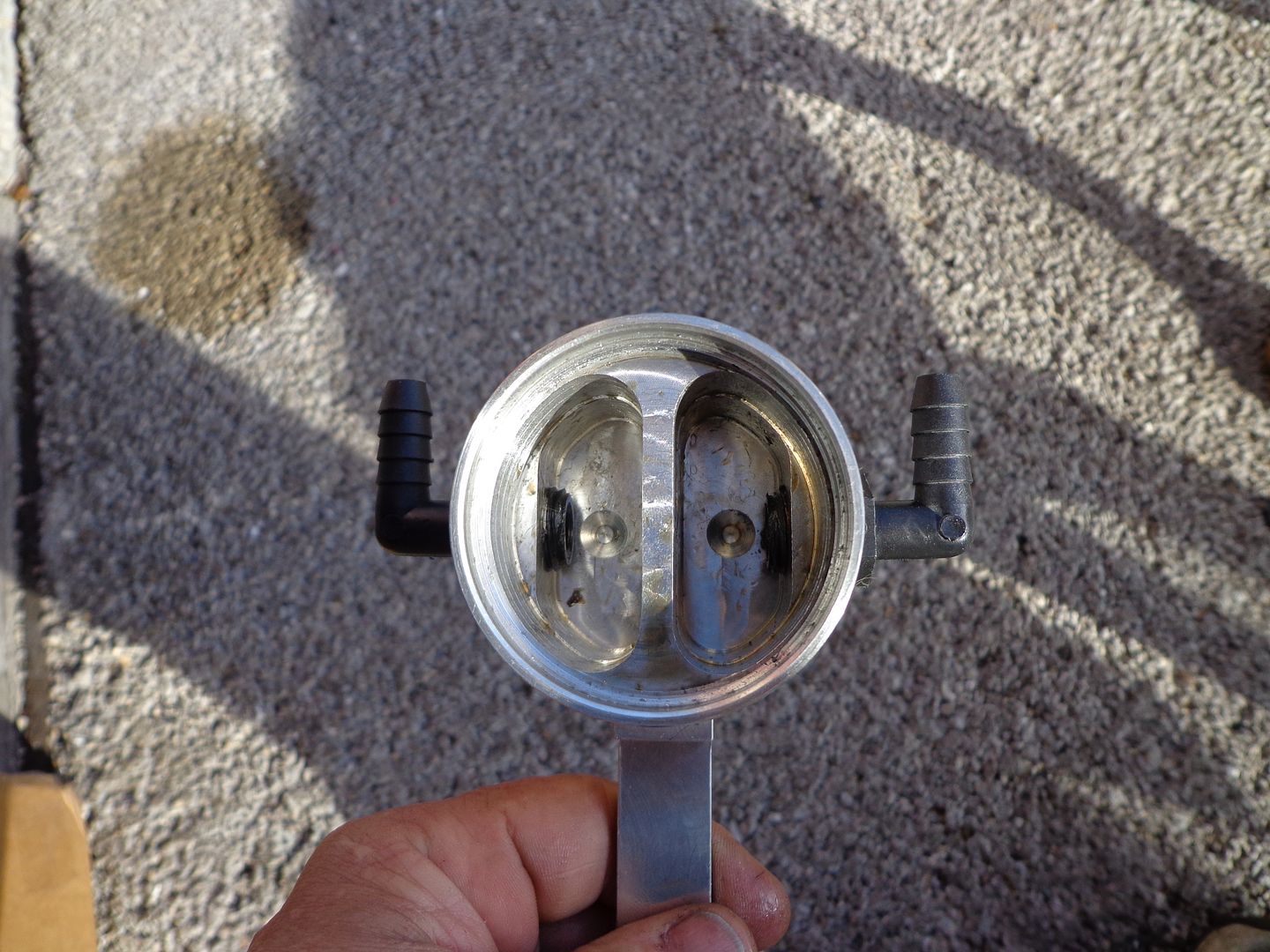
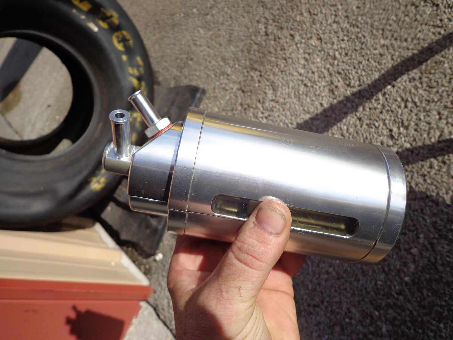
I’ve had a UPR catch can on my 5.0 since last summer. It catches a lot, especially in the cold months. But I’ll get right to my test. I added an RX can inline after my UPR can to see if the UPR was missing anything. And if it was allowing some to pass through, was it enough for the RX to catch anything? I don’t drive a lot of miles regularly since my F150 is not a daily driver, so my results will take some time. This thread is to document how I set it up and what I catch over time.
I installed the RX can just as the directions explained, but I routed the hoses differently. I left my UPR can right where it’s been for months, but rerouted one hose. I left the hose from the passenger side of the engine to the inlet of the UPR can. Then a new hose from UPR can outlet, routed to the inlet of the RX can. The RX outlet hose goes back to the engine. The PCV exhaust now flows from the engine, through the UPR, then through the RX, and finally back up to the engine intake.
Before installing everything for the test, I cleaned the UPR can thoroughly. The bottom of the can (inside) was covered with a thin layer of stiff sludge that I could only clean out using gas. I’m glad that was caught, along with the ounces of oil, water, etc, over the months I’ve been emptying it. But I was surprised at the outlet hose from the UPR can. It was wet with oil. Obviously some was getting through the can and back to my intake. I’ve never let the can get close to half full before emptying it. Nearly every time I’ve emptied it, there was 1/4“ or less in the bottom. I’m noting this in case someone thinks I left the UPR get overfilled and it flowed through. Nevertheless, I started this test after cleaning everything for a fresh start.
I plan to leave this setup on for a thousand miles or so, and report my findings from each can.
1st picture: UPR can as it was originally installed.
2nd: CleanUPR can.
3rd: RX can installed. The hose in the top center of the can is the inlet. The outlet hose on the right has a check valve.
4th: Engine outlet to UPR inlet on left of can. UPR outlet on right side of can routed around (smaller hose) to the RX inlet. You can also see the other smaller hose coming back up from the RX can and ending at the intake on the engine.
Report 2:
I thought I'd add a post to keep this thread alive since it is taking me awhile to get enough miles on the truck for valid results. Now that spring weather is finally arriving, I haven't been putting as many miles on it since I'm busy. But I have around 600 miles on the test set up so far. I emptied the cans recently and recorded the volumes to date. I'd like to wait until I get to 1000 miles before posting the results from the test, but I'll give some preliminary feedback.
- Emptying process -
First the UPR. I'm used to emptying the UPR can regularly, so it's not a big deal to unscrew, guide the can out from between the hoses, pour it out, guide it back in between the hoses, get it lined up carefully (so I don't cross thread the soft aluminum) and screw it back up snug. All that takes less than a few minutes so it's rather easy.
Now the RX can. Raise the hood, hold an empty water bottle under the drain tube, open the valve, close the valve, close the hood. I kid you not, it takes no more time than it took to read those steps. I knew it would be easy to empty, but it is ridiculously easy.
_ The weather so far -
During the first week of the test we had winter weather, with some snow. Since then we have had mild weather. Temperatures are in the 50's and 60's most days.
- What they caught so far -
I won't share the amounts yet, but I'll give some info. The UPR can has caught a 'mostly oil with a bit of water' mixture so far. The RX can (in line after the UPR) has had just the opposite. It's collected mostly water or fuel, with some oil mixed in.
I emptied the UPR first, and I would estimate it has collected the normal amount compared to what it usually does I empty it. I was pleased that my set up with 2 cans didn't seem to change the normal flow and collection I was used to seeing with just the UPR can. When I was about the turn the valve to empty the RX, I paused to a few seconds wondering if anything would come out. After all it was a new can that would need to get some oil/water coated on the inside before there would be enough to drip to the bottom (The UPR can had been in use for many months and although I cleaned the can I did not rinse off the filter material). Plus I wondered if the valve of the RX can protruded up into the can, and if it required some liquid to collect before there was enough to spill over that valve nipple and exit the can. Then I opened the valve and I had to smile when I had some liquid drain out. I thought all along that if it caught more than 10% of what the UPR was collecting, I would be surprised. It's still early in the test, and I would like to redo the test after reversing the order of the cans later, but I am surprised so far. I'm hoping to get more miles on the truck soon so I can wrap up this phase of the test.
Report 3:
1000 Miles of Testing Results
- The Weather has been warmer lately. So the test began with sub freezing temperatures, and gradually increased through the 70's and topped off in the mid 80's yesterday. I couldn't have asked for a better range of temperatures for this test.
- What they caught was astounding to me. UPR was first in line, with the RX after it to catch anything the UPR might miss.
The UPR stayed on track with what it has been accumulating for many months. Each time I emptied them, it had about the same amount. It's contents were mostly oil which smelled like used oil. It caught 17cc total which is just under 3 1/2 tsp.
The RX had more than the UPR each time I emptied them. It's contents were an oil/fuel/water type mix that had a much stronger odor. Not a fuel smell, but a sharper chemical smell compared to the odor of used oil. It caught a total of 67cc which is just over 13 1/2 tsp.
- Final totals:
UPR - 17cc
RX - 67cc
The RX can caught 4 times the amount the UPR can caught, after the UPR can removed what it could. I said from the beginning I would be surprised if the RX can could pull 10% of what the UPR caught, since it was second in line. If someone told me it would catch an equal amount I would have said **. For it to catch 4 times what the UPR can caught is unreal.
Report 4:
The routing of cans has been reversed so the second phase of the test is underway. I cleaned the cans and hoses so neither has an advantage. I also checked the inside of the hoses as I disassembled everything. The exit hose from the UPR was dripping with oil and it made a mess as I took it apart. The exit hose from the UPR was clean and dry. It still looked new. That is what prompted me to clean all the hoses before starting this phase. Is the double can routing helping the second can that much, or is one can that much better. Time will tell again.
Report 5:
And now back to our regularly scheduled programming…
Phase 2 is almost complete now, thanks to some extra mileage for work. I'll report on that soon and begin phase 3.
As I said above, UPR shipped parts for me to do phase 3 of the test. I bought my UPR can in June, and they changed the can slightly since then. The new diffuser/extension will only fit cans made after that, so they shipped a full new kit to test. Thank you UPR for helping with this, and for your input in this thread.
After shipping the kit, Joe@UPR asked me to remove the mesh from the exit side of my existing can for the remainder of phase 2, and to remove the mesh from the exit side of the new can before starting phase 3. I removed it from both (phase 2 was half way done when I removed it from the existing can). When I was removing the mesh from the short side of the new can (in preparation for phase 3), I realized the diffuser was assembled backwards. For our 5.0 F150's the long side of the diffuser must be on the passenger side of the can when installed. I disassembled, removed the mesh packed up in the can top on the exit/passenger side, and reassembled the can with diffuser. For anyone who might have received their cans assembled by UPR, you should check to see if it was assembled correctly before installing. (EDIT: Joe notes below they assemble the cans for shipping, and all cans should be assembled for your own installation needs) I also had a small piece of the stainless steel mesh (1/8") drop out when I was doing that. I wasn't thrilled with that so I unrolled, and lightly tapped the mesh in case there were any other loose pieces, but there weren't. A quick note on the UPR kit... it is much improved since I bought mine. The hoses are pre cut to the proper lengths, the elbow fittings are nickel rather than plastic, and they include Ford OEM snap on valve cover and intake fittings.
More to come soon!
Report 6:
Test Results
- I'll summarize the test to date. The first phase was to test the UPR vs the RX catch cans on a 5.0, both base models, with the UPR first in line and RX installed to catch anything the UPR missed. Those first phase results were: UPR - 17cc, RX - 67cc. The 'first in line' UPR caught 20% of the total volume. See post 37 in this thread for more details. The cans were cleaned and reinstalled in reverse order for phase 2, RX first and then UPR.
Phase 2 Test Results
- The Weather has been average northern Ohio spring weather. Some rain, fog, cool nights, warm and hot days.
- Driving has been about the same through both phases. I good mix of rural roads, some small towns, highways, and approximately 40% of the miles on interstates at 65 - 80mph. Mostly average style driving, with a few very heavy accelerations mixed in. A little heavy hauling, and no towing.
- What they caught this time might have been predicted by some (after the results of phase 1). RX was first in line, with the UPR after it to catch anything the RX might miss.
The combined volume of gunk was half of that caught in the first phase. The first phase had some cold weather which accounted for more water in the mix and the higher volume.
The contents from the RX can was mostly oil/fuel, and had a strong chemical/solvent smell again. It caught 35.5cc total which is approximately 7 1/8 tsp.
The UPR can caught about the same mix of oil/fuel, but didn't smell quite as strong. Halfway through this phase, Joe@UPR asked me to remove the mesh on the exit side of the UPR can. I did that, but noticed no difference in what it was catching. But since it was second in line, and there was little to catch, that's understandable. The UPR can caught 1.75cc total which is approximately 1/3 tsp. With so little collecting this time, I monitored the contents of the UPR can but didn't empty it until the end of the test.
- Phase 2 Totals:
RX - 35.5cc
UPR - 1.75cc
- Other tidbits include the 'first in line' RX can caught 95% of the total volume. The exit hoses were very clean from both cans. The last few tanks of gas have produced slightly higher than my normal MPGs, but it's too early to tell on that (more to follow after phase 3).
-Phase 3, using the UPR can extension and diffuser, is underway. Details will follow.
Final Test Results
- I'll summarize the test phases. The first phase was to test the UPR vs the RX catch cans on a 5.0, both base models, with the UPR first in line and RX installed to catch anything the UPR missed. Those first phase results were: UPR - 17cc, RX - 67cc. The 'first in line' UPR caught 20% of the total volume. See post 37 in this thread for more details on phase 1. The cans were cleaned and reinstalled in reverse order for phase 2, RX first and then UPR. The second phase results were: RX - 35.50cc, UPR - 1.75cc. The 'first in line' RX caught 95% of the total volume. See post 143 for more details on phase 2.
Phase 3 Test Results
- This time the UPR can was first in line as in phase 1, but it had the new can extension and diffuser added. It also had the mesh material removed from the exit side of the can.
- The Weather has been average northern Ohio early summer weather. Some rain with warm and hot days.
- Driving has been a good mix of rural roads, some small towns, highways, and approximately 60% of the miles on interstates at 65 - 80mph. Mostly average style driving, some steep hill climbs, and some very heavy accelerations mixed in. A little heavy hauling again, and no towing. I'll add some more thoughts on driving and MPGs below.
- What they caught was a mixed bag. UPR was first in line, with the RX after it to catch anything the extended UPR might miss.
The combined volume of gunk was down from the last phase, again. I assume it is due to the warmer weather and maybe my engine is using less oil with more miles? Either way, my test looks at the percent each can catches, compared to the total caught for that phase, so the volume isn't critical.
The contents from the extended UPR can was mostly oil, and had a used oil smell. The UPR caught 14.75cc which is approximately 3 tsp.
The RX can caught a fuel/water/oil mix. It smelled much more harsh again. The RX can caught 16.00cc which is approximately 3 1/4 tsp.
- Phase 3 Totals:
UPR - 14.75cc (48%)
RX - 16.00cc (52%)
- Other thoughts on the results. The contents of each phase showed me the RX does a better job of removing more than oil. It always contained more water/fuel type liquids, while the UPR contained mostly oil. I don't know if it is due to the can design, the 'out front' mounting style of the RX, or both.
For anyone buying or thinking of upgrading their UPR can, I strongly recommend figuring out how to mount it out front, and would definitely add the valve that Joe@UPR is offering. I really think the 'out front' cooling effect will help it catch even more, and the valve would be worth the price for ease of emptying it. Having the RX can to compare to when emptying, the front mount and valve are no brainers.
As I said at the end of phase 2, my MPGs have increased slightly. I have done nothing different to my truck over the past year, other than adding the RX can to the UPR for this test. My driving style is very similar from tank to tank, I fill up at the same stations, etc. But since having both cans in series, and essentially removing 95% or more of the PCV byproducts, my MPGs have increased. Up to that point my lifetime MPGs were 17.5. Nearly every tank for the past year gave me the same results, 17.5. I would have some trips that would net 20 MPG, but the other short trips would always pull it back down for the same tank average - close to 17.5. My recent tank averages have all been over 18 MPG, with a few over 19, and as high as 19.5. My last tank included hauling approximately 1000 lbs of payload, through some long hills/mountains of PA, and I got 18.8 MPG. It could be the summer fuel mix combined with an engine that is broken in, but the timing is peculiar. Whatever the reason, I like it!
Thank you Eco Tuner (Tuner Boost) and Joe@UPR for your support, feedback, and willingness to listen to open criticism and suggestions through this test. Looking back though this thread today, I realized how rare it is to get input and support from competing manufacturers, through a comparison test like this. We have all learned quite a bit, and have real data to help make decisions. Hats off to you both!
Note, UPR made updates mid test as the results were not coming out as they had planned, and did make improvements.


The only way to really know is to test the can. Take any can and install it. Now install one of the ones that do catch all or nearly all the gunk in line after the can your testing. Then do so in reverse. This will give you an accurate result. Here is one done by a UPR customer (same can as Moroso, Billet Prototypes, and a few dozen others made by one manufacturer but with tons of brand labels on them) with UPR supporting the customer during the test over several months and thousands of miles (we did not have anything to do with this except answer tech questions). Follow it closely and this can be done with any can to see how effective it is, or if it just allows most to pass right through. Most assume the can they chose is doing a good job and never test to see just how good. This was done on a 5.0 F150, and the person doing the test did it in a very controlled and detailed manner:
5.0 UPR vs RX Catch Can Effectiveness Test
I’ve had a UPR catch can on my 5.0 since last summer. It catches a lot, especially in the cold months. But I’ll get right to my test. I added an RX can inline after my UPR can to see if the UPR was missing anything. And if it was allowing some to pass through, was it enough for the RX to catch anything? I don’t drive a lot of miles regularly since my F150 is not a daily driver, so my results will take some time. This thread is to document how I set it up and what I catch over time.
I installed the RX can just as the directions explained, but I routed the hoses differently. I left my UPR can right where it’s been for months, but rerouted one hose. I left the hose from the passenger side of the engine to the inlet of the UPR can. Then a new hose from UPR can outlet, routed to the inlet of the RX can. The RX outlet hose goes back to the engine. The PCV exhaust now flows from the engine, through the UPR, then through the RX, and finally back up to the engine intake.
Before installing everything for the test, I cleaned the UPR can thoroughly. The bottom of the can (inside) was covered with a thin layer of stiff sludge that I could only clean out using gas. I’m glad that was caught, along with the ounces of oil, water, etc, over the months I’ve been emptying it. But I was surprised at the outlet hose from the UPR can. It was wet with oil. Obviously some was getting through the can and back to my intake. I’ve never let the can get close to half full before emptying it. Nearly every time I’ve emptied it, there was 1/4“ or less in the bottom. I’m noting this in case someone thinks I left the UPR get overfilled and it flowed through. Nevertheless, I started this test after cleaning everything for a fresh start.
I plan to leave this setup on for a thousand miles or so, and report my findings from each can.
1st picture: UPR can as it was originally installed.
2nd: CleanUPR can.
3rd: RX can installed. The hose in the top center of the can is the inlet. The outlet hose on the right has a check valve.
4th: Engine outlet to UPR inlet on left of can. UPR outlet on right side of can routed around (smaller hose) to the RX inlet. You can also see the other smaller hose coming back up from the RX can and ending at the intake on the engine.
Report 2:
I thought I'd add a post to keep this thread alive since it is taking me awhile to get enough miles on the truck for valid results. Now that spring weather is finally arriving, I haven't been putting as many miles on it since I'm busy. But I have around 600 miles on the test set up so far. I emptied the cans recently and recorded the volumes to date. I'd like to wait until I get to 1000 miles before posting the results from the test, but I'll give some preliminary feedback.
- Emptying process -
First the UPR. I'm used to emptying the UPR can regularly, so it's not a big deal to unscrew, guide the can out from between the hoses, pour it out, guide it back in between the hoses, get it lined up carefully (so I don't cross thread the soft aluminum) and screw it back up snug. All that takes less than a few minutes so it's rather easy.
Now the RX can. Raise the hood, hold an empty water bottle under the drain tube, open the valve, close the valve, close the hood. I kid you not, it takes no more time than it took to read those steps. I knew it would be easy to empty, but it is ridiculously easy.
_ The weather so far -
During the first week of the test we had winter weather, with some snow. Since then we have had mild weather. Temperatures are in the 50's and 60's most days.
- What they caught so far -
I won't share the amounts yet, but I'll give some info. The UPR can has caught a 'mostly oil with a bit of water' mixture so far. The RX can (in line after the UPR) has had just the opposite. It's collected mostly water or fuel, with some oil mixed in.
I emptied the UPR first, and I would estimate it has collected the normal amount compared to what it usually does I empty it. I was pleased that my set up with 2 cans didn't seem to change the normal flow and collection I was used to seeing with just the UPR can. When I was about the turn the valve to empty the RX, I paused to a few seconds wondering if anything would come out. After all it was a new can that would need to get some oil/water coated on the inside before there would be enough to drip to the bottom (The UPR can had been in use for many months and although I cleaned the can I did not rinse off the filter material). Plus I wondered if the valve of the RX can protruded up into the can, and if it required some liquid to collect before there was enough to spill over that valve nipple and exit the can. Then I opened the valve and I had to smile when I had some liquid drain out. I thought all along that if it caught more than 10% of what the UPR was collecting, I would be surprised. It's still early in the test, and I would like to redo the test after reversing the order of the cans later, but I am surprised so far. I'm hoping to get more miles on the truck soon so I can wrap up this phase of the test.
Report 3:
1000 Miles of Testing Results
- The Weather has been warmer lately. So the test began with sub freezing temperatures, and gradually increased through the 70's and topped off in the mid 80's yesterday. I couldn't have asked for a better range of temperatures for this test.
- What they caught was astounding to me. UPR was first in line, with the RX after it to catch anything the UPR might miss.
The UPR stayed on track with what it has been accumulating for many months. Each time I emptied them, it had about the same amount. It's contents were mostly oil which smelled like used oil. It caught 17cc total which is just under 3 1/2 tsp.
The RX had more than the UPR each time I emptied them. It's contents were an oil/fuel/water type mix that had a much stronger odor. Not a fuel smell, but a sharper chemical smell compared to the odor of used oil. It caught a total of 67cc which is just over 13 1/2 tsp.
- Final totals:
UPR - 17cc
RX - 67cc
The RX can caught 4 times the amount the UPR can caught, after the UPR can removed what it could. I said from the beginning I would be surprised if the RX can could pull 10% of what the UPR caught, since it was second in line. If someone told me it would catch an equal amount I would have said **. For it to catch 4 times what the UPR can caught is unreal.
Report 4:
The routing of cans has been reversed so the second phase of the test is underway. I cleaned the cans and hoses so neither has an advantage. I also checked the inside of the hoses as I disassembled everything. The exit hose from the UPR was dripping with oil and it made a mess as I took it apart. The exit hose from the UPR was clean and dry. It still looked new. That is what prompted me to clean all the hoses before starting this phase. Is the double can routing helping the second can that much, or is one can that much better. Time will tell again.
Report 5:
And now back to our regularly scheduled programming…
Phase 2 is almost complete now, thanks to some extra mileage for work. I'll report on that soon and begin phase 3.
As I said above, UPR shipped parts for me to do phase 3 of the test. I bought my UPR can in June, and they changed the can slightly since then. The new diffuser/extension will only fit cans made after that, so they shipped a full new kit to test. Thank you UPR for helping with this, and for your input in this thread.
After shipping the kit, Joe@UPR asked me to remove the mesh from the exit side of my existing can for the remainder of phase 2, and to remove the mesh from the exit side of the new can before starting phase 3. I removed it from both (phase 2 was half way done when I removed it from the existing can). When I was removing the mesh from the short side of the new can (in preparation for phase 3), I realized the diffuser was assembled backwards. For our 5.0 F150's the long side of the diffuser must be on the passenger side of the can when installed. I disassembled, removed the mesh packed up in the can top on the exit/passenger side, and reassembled the can with diffuser. For anyone who might have received their cans assembled by UPR, you should check to see if it was assembled correctly before installing. (EDIT: Joe notes below they assemble the cans for shipping, and all cans should be assembled for your own installation needs) I also had a small piece of the stainless steel mesh (1/8") drop out when I was doing that. I wasn't thrilled with that so I unrolled, and lightly tapped the mesh in case there were any other loose pieces, but there weren't. A quick note on the UPR kit... it is much improved since I bought mine. The hoses are pre cut to the proper lengths, the elbow fittings are nickel rather than plastic, and they include Ford OEM snap on valve cover and intake fittings.
More to come soon!
Report 6:
Test Results
- I'll summarize the test to date. The first phase was to test the UPR vs the RX catch cans on a 5.0, both base models, with the UPR first in line and RX installed to catch anything the UPR missed. Those first phase results were: UPR - 17cc, RX - 67cc. The 'first in line' UPR caught 20% of the total volume. See post 37 in this thread for more details. The cans were cleaned and reinstalled in reverse order for phase 2, RX first and then UPR.
Phase 2 Test Results
- The Weather has been average northern Ohio spring weather. Some rain, fog, cool nights, warm and hot days.
- Driving has been about the same through both phases. I good mix of rural roads, some small towns, highways, and approximately 40% of the miles on interstates at 65 - 80mph. Mostly average style driving, with a few very heavy accelerations mixed in. A little heavy hauling, and no towing.
- What they caught this time might have been predicted by some (after the results of phase 1). RX was first in line, with the UPR after it to catch anything the RX might miss.
The combined volume of gunk was half of that caught in the first phase. The first phase had some cold weather which accounted for more water in the mix and the higher volume.
The contents from the RX can was mostly oil/fuel, and had a strong chemical/solvent smell again. It caught 35.5cc total which is approximately 7 1/8 tsp.
The UPR can caught about the same mix of oil/fuel, but didn't smell quite as strong. Halfway through this phase, Joe@UPR asked me to remove the mesh on the exit side of the UPR can. I did that, but noticed no difference in what it was catching. But since it was second in line, and there was little to catch, that's understandable. The UPR can caught 1.75cc total which is approximately 1/3 tsp. With so little collecting this time, I monitored the contents of the UPR can but didn't empty it until the end of the test.
- Phase 2 Totals:
RX - 35.5cc
UPR - 1.75cc
- Other tidbits include the 'first in line' RX can caught 95% of the total volume. The exit hoses were very clean from both cans. The last few tanks of gas have produced slightly higher than my normal MPGs, but it's too early to tell on that (more to follow after phase 3).
-Phase 3, using the UPR can extension and diffuser, is underway. Details will follow.
Final Test Results
- I'll summarize the test phases. The first phase was to test the UPR vs the RX catch cans on a 5.0, both base models, with the UPR first in line and RX installed to catch anything the UPR missed. Those first phase results were: UPR - 17cc, RX - 67cc. The 'first in line' UPR caught 20% of the total volume. See post 37 in this thread for more details on phase 1. The cans were cleaned and reinstalled in reverse order for phase 2, RX first and then UPR. The second phase results were: RX - 35.50cc, UPR - 1.75cc. The 'first in line' RX caught 95% of the total volume. See post 143 for more details on phase 2.
Phase 3 Test Results
- This time the UPR can was first in line as in phase 1, but it had the new can extension and diffuser added. It also had the mesh material removed from the exit side of the can.
- The Weather has been average northern Ohio early summer weather. Some rain with warm and hot days.
- Driving has been a good mix of rural roads, some small towns, highways, and approximately 60% of the miles on interstates at 65 - 80mph. Mostly average style driving, some steep hill climbs, and some very heavy accelerations mixed in. A little heavy hauling again, and no towing. I'll add some more thoughts on driving and MPGs below.
- What they caught was a mixed bag. UPR was first in line, with the RX after it to catch anything the extended UPR might miss.
The combined volume of gunk was down from the last phase, again. I assume it is due to the warmer weather and maybe my engine is using less oil with more miles? Either way, my test looks at the percent each can catches, compared to the total caught for that phase, so the volume isn't critical.
The contents from the extended UPR can was mostly oil, and had a used oil smell. The UPR caught 14.75cc which is approximately 3 tsp.
The RX can caught a fuel/water/oil mix. It smelled much more harsh again. The RX can caught 16.00cc which is approximately 3 1/4 tsp.
- Phase 3 Totals:
UPR - 14.75cc (48%)
RX - 16.00cc (52%)
- Other thoughts on the results. The contents of each phase showed me the RX does a better job of removing more than oil. It always contained more water/fuel type liquids, while the UPR contained mostly oil. I don't know if it is due to the can design, the 'out front' mounting style of the RX, or both.
For anyone buying or thinking of upgrading their UPR can, I strongly recommend figuring out how to mount it out front, and would definitely add the valve that Joe@UPR is offering. I really think the 'out front' cooling effect will help it catch even more, and the valve would be worth the price for ease of emptying it. Having the RX can to compare to when emptying, the front mount and valve are no brainers.
As I said at the end of phase 2, my MPGs have increased slightly. I have done nothing different to my truck over the past year, other than adding the RX can to the UPR for this test. My driving style is very similar from tank to tank, I fill up at the same stations, etc. But since having both cans in series, and essentially removing 95% or more of the PCV byproducts, my MPGs have increased. Up to that point my lifetime MPGs were 17.5. Nearly every tank for the past year gave me the same results, 17.5. I would have some trips that would net 20 MPG, but the other short trips would always pull it back down for the same tank average - close to 17.5. My recent tank averages have all been over 18 MPG, with a few over 19, and as high as 19.5. My last tank included hauling approximately 1000 lbs of payload, through some long hills/mountains of PA, and I got 18.8 MPG. It could be the summer fuel mix combined with an engine that is broken in, but the timing is peculiar. Whatever the reason, I like it!
Thank you Eco Tuner (Tuner Boost) and Joe@UPR for your support, feedback, and willingness to listen to open criticism and suggestions through this test. Looking back though this thread today, I realized how rare it is to get input and support from competing manufacturers, through a comparison test like this. We have all learned quite a bit, and have real data to help make decisions. Hats off to you both!
Note, UPR made updates mid test as the results were not coming out as they had planned, and did make improvements.
If you'll go back and read all of @Turbo Boost 's posts you find an extensive exposition on why a "drain back" system as opposed to a "catch can / removal" system is less desirable for long-term operation due to acid and water contamination in the crankcase vapors.Here is the Powell LNF PCV Anti-coking drain back system
The seperator has a filter, and a check valve, and is designed to maintain OEM design intent vacuum through the PCV system..... .
@Turbo Boost also makes an argument for not maintaining the strictly OEM FE vacuum scheme but improving it to provide crankcase vapor scavenging under boost conditions (which the OEM system does not according to him). From review of several vendor websites offering Ford Ecoboost specific solutions for the potential coking problem there seems to be growing consensus on both counts.
I hope we can avoid a rehash of those discussions at this point in the thread. (edit - dang, I type too slow ;-)
Braided SS lines and colorful AN fittings look nice but for me that's an expense I don't need and "attention" I don't want for my daily driver street FE which is subject to 'casual visual' annual inspection. Given the pressures involved in the PCV system the rating of those hoses/fittings is total overkill, though the aesthetic is undeniably nice for a race & show motor.
See attached pic FYI, again the devil is in the details.I haven't seen the 2.0 without the plastic engine cover, but I bet it is 99% the same setup just a different manufacture.
Also those cheap canisters only have steel wool inside "to grab oil and particles", not really the best method.
As far as I can tell none of the alternatives suggested by @Turbo Boost is a "cheap" solution with only steel wool. Some may use coarse metal 'wool' as a "coalescing filter media" to help vapor-state contaminants condense into droplets so they'll drop-out of suspension in the vapor stream. I may not know boo about PCV systems but I do know that coalescing filters using coarse metal 'wool' material are a well-established and proven tool for facilitating removal of vapor-state contaminants in industrial gas-streams.
Joined
·
2,051 Posts
I didn't read all of his posts. Which then leads me now knowing what he has fully done/researched. I'm all for something that works better than the one I was informed of by the raceshop.
with turbo boost's knowledge and skill, via his posts and pics, I'd believe it will be a very good solution vs the ebay can. I posted what I knew before fully reading his. I don't think drain back is the worst, but I could see it being an issue.
with turbo boost's knowledge and skill, via his posts and pics, I'd believe it will be a very good solution vs the ebay can. I posted what I knew before fully reading his. I don't think drain back is the worst, but I could see it being an issue.
Joined
·
809 Posts
How many mile does it take before doing any noticeable damage? I ask for 2 reasons. First, there is a 5/50,000 drive train warranty. Second, I usually trade my cars well before that, the last two with less than 10,000 miles.
But, even if it's covered under warranty, I don't want to find myself stuck on the side of the road.
---
But, even if it's covered under warranty, I don't want to find myself stuck on the side of the road.
---
Please see attached. I realize that the pic probably isn't sufficient for a detailed routing plan but it gives you an idea of access issues and relative locations of key points.Get good pics up and a diagram & I can guide any on proper routing. .....
Perhaps start with an indication of where catch-can-to-engine connections need to be made on the schematic with discussion of which connecting tubes, if any, need to have a particular 'slope' for fluid flow to or from the catch can?
A 'dual check valve' catch can system is needed to provide optimal removal of crankcase contaminants under boost along with eliminating/reducing the coking problem, but a 'single check-valve catch-can system' is all that's necessary if the only objective is addressing the intake valve coking problem, is that correct?
Attachments
-
 267.3 KB Views: 1,807
 -
 100.2 KB Views: 594
How many mile does it take before doing any noticeable damage? I ask for 2 reasons. First, there is a 5/50,000 drive train warranty. Second, I usually trade my cars well before that, the last two with less than 10,000 miles.
But, even if it's covered under warranty, I don't want to find myself stuck on the side of the road.---[/QUOTE
Bill I don't think it will leave you on the side of the road. The main symptoms are rough idle and stalling at idle, but it should restart. Lower fuel economy is another symptom. I think your driving style has a lot to do with when and if you will have a problem with carbon build-up.
I don't know if you have seen the five F150 ecoboost torture test video's yet, if you haven't here's the link: F-150 EcoBoost Twin Turbo V6 Torture Test
They take a 3.5L ecoboost V6 in an f150 and run it over 160,000 miles dyno it after then tear it down with no apparent carbon build up issues.
Mark
Joined
·
17 Posts
With a NA engine, yes, that is correct. With a turbo or centrifugal FI application that pressurizes the intake manifold while in boost, the dual valve configuration is needed to correct the evacuation so it is taking place at boost non-boost and boost operation or the crankcase pressure builds and allows the contaminates to "back flow) out the cleanside into the turbo inlet pipe.Please see attached. I realize that the pic probably isn't sufficient for a detailed routing plan but it gives you an idea of access issues and relative locations of key points.
Perhaps start with an indication of where catch-can-to-engine connections need to be made on the schematic with discussion of which connecting tubes, if any, need to have a particular 'slope' for fluid flow to or from the catch can?Good questions. The can can be mounted anywhere that it is upright. Since vacuum is the source for evacuation, and the cooler the location the more effective for the condensation process. A good can uses coalescing material and condensing while avoiding the pull through the Bernoulli effect allows.
A 'dual check valve' catch can system is needed to provide optimal removal of crankcase contaminants under boost along with eliminating/reducing the coking problem, but a 'single check-valve catch-can system' is all that's necessary if the only objective is addressing the intake valve coking problem, is that correct?
Mark is correct. Won't leave you on the side of the road unless enough of the accumulated gunk in the intercooler enters the combustion chamber. If it does, then hydro-lock can occur (see the NTSB investigation into the v6 ecoboosts) breaking pistons and rods.How many mile does it take before doing any noticeable damage? I ask for 2 reasons. First, there is a 5/50,000 drive train warranty. Second, I usually trade my cars well before that, the last two with less than 10,000 miles.
Coking reaches the point of disrupting air flow for uniform A/F mixture in each cylinder at usually around 10-12 k miles, but a simple look at your own valves will tell volumes and can be shared here for all to see. The real damage is just premature valve guide wear or in the event of chunks breaking off and sticking between the valve and seat, or traveling through the exhaust and hitting the hot side turbine blades. Wear of the internals is gradual over time and won't be noticed in most cases until 50-100k miles. Fuel economy degradation
But, even if it's covered under warranty, I don't want to find myself stuck on the side of the road.---[/QUOTE
Bill I don't think it will leave you on the side of the road. The main symptoms are rough idle and stalling at idle, but it should restart. Lower fuel economy is another symptom. I think your driving style has a lot to do with when and if you will have a problem with carbon build-up.
I don't know if you have seen the five F150 ecoboost torture test video's yet, if you haven't here's the link: F-150 EcoBoost Twin Turbo V6 Torture Test
They take a 3.5L ecoboost V6 in an f150 and run it over 160,000 miles dyno it after then tear it down with no apparent carbon build up issues.
Mark
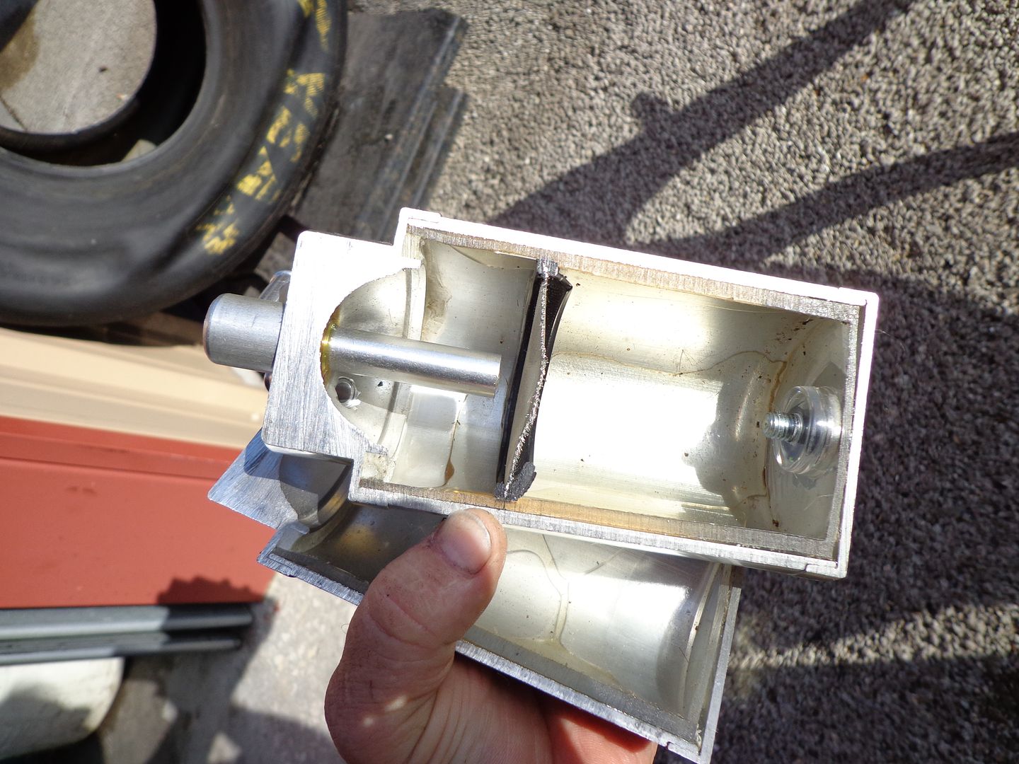
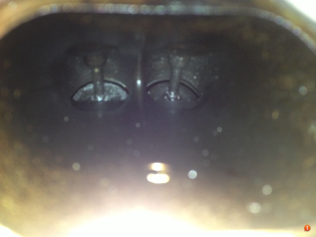
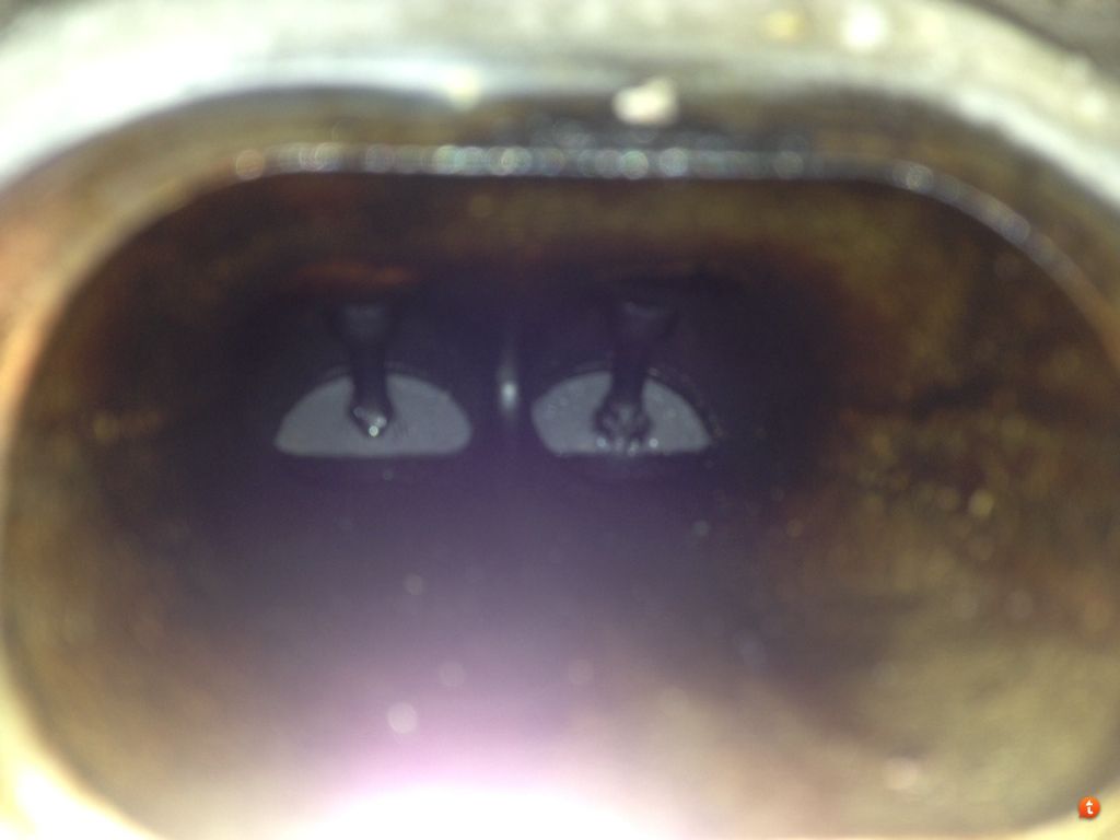
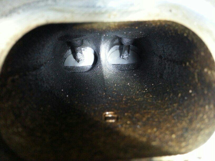
As for the torture test, no one but the engineers involved know how it was maintained, but the video shows the heads removed and does not show the back side of the valves....even so, we tear these down all the time and perform manual valve cleanings at 10-20-50k miles, and in every case there is substantial coking on the backsides of the valves. Here are some pictures to show:
![Image]()
![Image]()
Here is the v6 version at 30 k miles:
![Image]()
![Image]()
![Image]()


Joined
·
17 Posts
Excellent pic and diagram. What you would change is the following:Please see attached. I realize that the pic probably isn't sufficient for a detailed routing plan but it gives you an idea of access issues and relative locations of key points.
Perhaps start with an indication of where catch-can-to-engine connections need to be made on the schematic with discussion of which connecting tubes, if any, need to have a particular 'slope' for fluid flow to or from the catch can?
A 'dual check valve' catch can system is needed to provide optimal removal of crankcase contaminants under boost along with eliminating/reducing the coking problem, but a 'single check-valve catch-can system' is all that's necessary if the only objective is addressing the intake valve coking problem, is that correct?
Cleanside is the tube that is on the rear of the cam cover, and where it runs currently is subject to suction from the turbo as it is in the turbo inlet pipe. It should be connected to the filtered portion of the main airbox. That won't be subject to much suction due to the dispersion of the filter element. The further down the turbo inlet tube the greater the suction. You want clean, filtered air to enter this tube to flush, and replace the foul vapors evacuated from the PCV/separator dirty (foul) side. So that is the first move. We prefer a cleanside separator be used, and that can replace the oil fill cap. This will trap any oil vapors that would travel through it when transitioning between non-boost and boost.
Then on the dirty side, the inlet of a oil separating can will connect to it. It should have a one way checkvalve as part of the assy, and this prevents boost from entering the crankcase. Then, one outlet of the can, with an additional checkvalve flowing away from the can will connect to the intake manifold vacuum post as shown in the diagram. The other outlet from the can, with oneway checkvalve flowing away from the can will then attache to the barb on the turbo inlet pipe that originally had the cleanside tube connected. This will then use the intake manifold vacuum to evacuate when in non-boost, and the turbo suction to evacuate when in boost. The cleanside should be drawing air from the filtered portion of the main air box (no unfiltered air ever into the crankcase) and you now have constant, steady, evacuation of the damaging compounds as soon as they enter the crankcase no matter if in boost or not. This will prevent the accumulated vapors from being pulled into the turbo inlet, and routes all vapors through the separating can correcting the lack of evacuation the OEM system creates. The OEM only uses the intake manifold vacuum for evacuation, and these turbos are very efficient and quick spooling, so most of the time your driving, there is no evacuation...only pressure building until it seeks an exit, and that is out the in...or out the cleanside, which you do not want.
I will be on the road to a race in TX tomorrow so won't have internet access, but will be back next Tue and will try to get on then for more questions.
Great interaction here, and thanks centex for the pic and diagram. You have a good understanding of this.
...... A 'dual check valve' catch can system is needed to provide optimal removal of crankcase contaminants under boost along with eliminating/reducing the coking problem, but a 'single check-valve catch-can system' is all that's necessary if the only objective is addressing the intake valve coking problem, is that correct?
Thanks for your patience as I try to understand this stuff. How does the dual valve catch can configuration address that 'cleanside' (valve cover breather) 'back-flow' situation when under boost? I thought that even with a dual valve configuration a separate cleanside separator was required to 'clean' that 'back flow' air stream?With a NA engine, yes, that is correct. With a turbo or centrifugal FI application that pressurizes the intake manifold while in boost, the dual valve configuration is needed to correct the evacuation so it is taking place at boost non-boost and boost operation or the crankcase pressure builds and allows the contaminates to "back flow) out the cleanside into the turbo inlet pipe. ...
EDIT - sorry, I was writing while you made the above post. Where ya racing in TX? Would really like to meet ya.
Turbo Boost, correct me if I'm wrong, but I dont think it would be a hydro-lock it would be more of a interference lock with carbon. Also while they didn't show the intake valves on the teardown in the torture test video's, they did do a dyno test and it came very close to original new engine figures at 160,000 plus miles. I'm sure Ford put this under the best light possible.
In the end I don't know why DI turbo engine manufactures don't install a product like yours from the start, or at least have it as an option. I'm just trying to figure out if the juice is worth the squeeze for something like this to the average buyer to get 150,000 - 200,000 miles out of one of these engine's.
Again I'm a car guy and would be interested in one with CARB certification, so please keep us posted on your progress.
Thank you for your posts they are very interesting and a good read.
Mark
Well we just purchased a 2014 Titanium 4WD 2.0L FE and this is all just a kick in the nuts. I was told to stay far away from any DI engines but my wife insisted on the Escape.
Now I guess I should have insisted on the Ugly Subaru Outback with the 2.5 Boxer engine. At least the Subaru is proven to go 200,000-300,000 miles with no issues.
Now that all the doctors have concluded that the 2.0 DI has about three years before it has to go under the knife or even a heart transplant what are the common people to do? I can only imagine what the trade in or resale value will be after 4 years 40,000 miles, pretty sad.
I like most everyone else have been reading about the horror stories of the DI technology and the problems that manufacturers are having.
I see that Ford has totally redesigned its current 2.0-liter EcoBoost engine after just four model years and will be phasing ours out. Hmmm I wonder why? More good news for me Ha- (the current 2.0 is built in Spain by the way).
The dealer loaned us a 2013 Escape with 37,000 miles on it while ours was being under coated and it ran like Total Crap. It would Constantly lunge forward and drop down a gear whenever I would give it a little throttle. I mentioned it to the dealer and he said it was off lease that they were going to look at it. Could be a totally different issue then the carbon issue but it makes me wonder. Could have been crappy gas I don’t know. Just hope I don’t have the same problem with ours at that mileage.
I have contacted the services managers of the four major Ford dealers here in town and asked them the question about their DI engines having carbon issues. They all told me that they have not seen any issues with their EcoBoost engines. Don’t know if this is ** or not.
We love the Escape for the short two weeks that we have had it. I guess I'm worried just like everyone else about the life of the engine, only time will tell. I will be keeping my fingers crossed and hoping for the best.
Thanks everyone for your awesome input- I will stay glued to this forum for sure
41 - 60 of 232 Posts
-
?
-
?
-
?
-
?
-
?
-
?
-
?
-
?
-
?
-
?
-
?
-
?
-
?
-
?
-
?
-
?
-
?
-
?
-
?
-
?
- posts
- 247K
- members
- 56K
- Since
- 2012
On Ford Escape Forum discover news, discussions, service tips, & technical help for your 2013+ Escape.